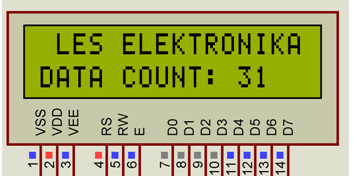
i keep getting some compile errors about LCD_DISP_ON_BLINK and 2, or 3 other lines. See the C include lcd.I also get solid block of squares in one line only but I can't get this even to compile. Generation of R/W signal through A8 address line. Memory mapped mode compatible with Kanda STK200, but supports also Library can be operated in memory mapped mode (LCD_IO_MODE=0) or inĤ-bit IO port mode (LCD_IO_MODE=1). Originally based on Volker Oth’s lcd library,Ĭhanged lcd_init(), added additional constants for lcd_command(),Īdded 4-bit I/O mode, improved and optimized code. Target: any AVR device, memory mapped mode only for AT90S4414/8515/Megaīasic routines for interfacing a HD44780U-based text lcd display #define LCD_E_PIN 4 /**< pin for Enable line */ #define LCD_E_PORT LCD_PORT /**< port for Enable line */ #define LCD_RW_PIN 5 /**< pin for RW line */ #define LCD_RW_PORT LCD_PORT /**< port for RW line */ #define LCD_RS_PIN 6 /**< pin for RS line */ #define LCD_RS_PORT LCD_PORT /**< port for RS line */ #define LCD_DATA3_PIN 0 /**< pin for 4bit data bit 3 */ #define LCD_DATA2_PIN 1 /**< pin for 4bit data bit 2 */ #define LCD_DATA1_PIN 2 /**< pin for 4bit data bit 1 */ #define LCD_DATA0_PIN 3 /**< pin for 4bit data bit 0 */

#define LCD_DATA3_PORT LCD_PORT /**< port for 4bit data bit 3 */ #define LCD_DATA2_PORT LCD_PORT /**< port for 4bit data bit 2 */

#define LCD_DATA1_PORT LCD_PORT /**< port for 4bit data bit 1 */ #define LCD_DATA0_PORT LCD_PORT /**< port for 4bit data bit 0 */ #define LCD_PORT PORTD /**< port for the LCD lines */ There you can define every dataline to every port. Is there no way to connect D4-D7 of the LCD-Module in the right order?Īnother way is, you use the LCD-Library from P. If you search in the file lcd.c for LCD_DATA_POS you’ll find it on several positions. But it’s a little difficult because the library supports only the ascending order of the ports Is my statement ok?). And that’s all! So you saw how easy is toĬustomize the library. This is done by #define LCD_E_POS PB4 So ‘E’ pin of LCD is connected to PORTD-6 It is PORTB so #define LCD_E B Then specify to which PIN of PORTB it is connected, The library uses advance 4-bit mode so DATA0-DATA-3 of LCD are not used, savingĤ MCU pins! Now set the port where you have connected LCD’s ‘E’ signal. Please note that LCD Data lines DATA0 to DATA3 are always unused only DATA4 to DATA7 are required. #define LCD_DATA_POS 3 // Because LCD DATA4 is connected to PD3 #define LCD_DATA D //Because we are using PORTD For example if you wise to connect like this. The LCD data lines D4 to D7 must be connected to consecutive pins starting from LCD_DATA_POS. Then set LCD_DATA_POS to the starting pin of data lines.


Set LCD_DATA to the port where you have connected the LCD data lines. Open lcd.h and find a section “LCD Connections” it looks like If you want to connect the LCD module to some different i/o ports of the MCU then you can do so easily. The library is designed to be fully customizable. Print some numbers for (i= 0 i< 99 i+= 1) Sample Program #include #include #include "lcd.h" void main() Now you know the basics of LCD interfacing lets jump to a sample program that will demonstrate the functions you learned. LCDWriteIntXY(x,y,num,field_length) įield_length : the length of field (see LCDWriteInt() function above). Similarly there is a function for integers.


 0 kommentar(er)
